
To prevent the surprises outlined in the previous section, you should always do two things:
■ Configure one switch as a Root Bridge in a determined fashion.
■ Configure another switch as a secondary Root Bridge, in case of a primary Root Bridge failure.
As the common reference point, the Root Bridge (and the secondary) should be placed near the center of the Layer 2 network. For example, a switch in the distribution layer would make a better Root Bridge choice than one in the access layer because more traffic is expected to pass through the distribution-layer devices. In a flat switched network (no Layer 3 devices), a switch near a server farm would be a more efficient Root Bridge than switches elsewhere. Most traffic will be destined to and from the server farm and will benefit from a predetermined, direct path.
If the switch can’t support 1,024 unique MAC addresses for its own use, the extended system ID is always enabled by default. Otherwise, the traditional method is enabled by default.
Switch(config)# spanning-tree extend system-id
Otherwise, you can use the traditional method by beginning the command with the no keyword.
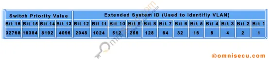
Switch(config)# spanning-tree vlan vlan-list priority bridge-priority The bridge-priority value defaults to 32,768, but you can also assign a value of 0 to 65,535. If STP extended system ID is enabled, the default bridge-priority is 32,768 plus the VLAN number. In that case, the value can range from 0 to 61,440, but only as multiples of 4,096. A lower bridge priority is preferable.
Switch(config)# spanning-tree vlan 5,100-200 priority 4096
This command is actually a macro on the Catalyst that executes several other commands. The result is a more direct and automatic way to force one switch to become the Root Bridge. Notice that the actual bridge priorities are not given in the command. Instead, the switch modifies its STP values according to the current values in use within the active network. These values are modified only once, when the macro command is issued. Use the primary keyword to make the switch attempt to become the primary Root Bridge. This command modifies the switch’s bridge priority value to become less than the bridge priority of the current Root Bridge. If the current root priority is more than 24,576, the local switch sets its priority to 24,576. If the current root priority is less than that, the local switch sets its priority to 4096 less than the current root.
For the secondary Root Bridge, the root priority is set to an artificially low value of 28,672. There is no way to query or listen to the network to find another potential secondary root simply because there are no advertisements or elections of secondary Root Bridges. Instead, the fixed secondary priority is used under the assumption that it will be less than the default priorities (32,768) that might be used on switches elsewhere. You can also modify the network diameter by adding the diameter keyword to this command. This modification is discussed further in the «Tuning Spanning-Tree Convergence» section later in the chapter.
As a final example, consider a switch that is currently using its default bridge priority for VLAN 100. In the extended system-id mode, the default priority is 32,768 plus 100 (the VLAN number). The output in Example 9-1 demonstrates this under the Bridge ID information. The default priority is greater than the current Root Bridge priority of 4200, so the local switch cannot become the root.
Example 9-1 Displaying the STP Bridge Priority Values
Switch# show spanning-tree vlan 100
Spanning tree enabled protocol ieee Root ID Priority 4200
Example 9-1 Displaying the STP Bridge Priority Values (Continued) Cost 4
Port 1 (GigabitEthernet0/1)
Hello Time 2 sec Max Age 20 sec Forward Delay 15 sec
Bridge ID Priority 32868 (priority 32768 sys-id-ext 100) Address 000c.8554.9a80
Now, the automatic method is used to attempt to make the switch become root for VLAN 100, using the command demonstrated in Example 9-2.
Example 9-2 Using a Macro Command to Configure a Root Bridge
Switch(config)# spanning-tree vlan 100 root primary
% Failed to make the bridge root for vlan 100
% It may be possible to make the bridge root by setting the priority
% for some (or all) of these instances to zero.
Switch(config)# spanning-tree vlan 100 priority 0 Remember that on switches that use an extended system ID, the bridge priority is the configured priority (multiple of 4,096) plus the VLAN number. Even though the priority was set to 0 with the previous command, the switch is actually using a value of 100—priority 0 plus VLAN number 100, as the output in Example 9-3 reveals.
Example 9-3 Displaying Bridge Priorities with Extended System IDs
Spanning tree enabled protocol ieee Root ID Priority 100
Address 000c.8554.9a80 This bridge is the root
Hello Time 2 sec Max Age 20 sec Forward Delay 15 sec continues
Example 9-3 Displaying Bridge Priorities with Extended System IDs (Continued)
Switch(config)# spanning-tree vlan 1 root primary vlan 1 bridge priority set to 24576 vlan 1 bridge max aging time unchanged at 20 vlan 1 bridge hello time unchanged at 2 vlan 1 bridge forward delay unchanged at 15
Be aware that this macro doesn’t guarantee that the switch will become the root and maintain that status. After the macro is used, it is entirely possible for another switch in the network to have its bridge priority configured to a lower value. The other switch would become the new root, displacing the switch that ran the macro.
On the root, it is usually good practice to directly modify the bridge priority to an artificially low value (even priority 1 or 0) with the spanning-tree vlan vlan-id priority bridge-priority command. This makes it more difficult for another switch in the network to win the Root Bridge election, unless it is manually configured with a priority that is even lower.
Continue reading here: Tuning the Root Path Cost
Was this article helpful?
Cisco Catalyst switches support three types of spanning-tree protocols: PVST+, PVRST+, and MSTP.
■ PVST+: Based on the 802.1D standard, this includes Cisco proprietary extensions, such as BackboneFast, UplinkFast, and PortFast, which improve STP convergence time.
■ PVRST+: Based on the 802.1w standard, this has a faster convergence than 802.1D.
■ MSTP (802.1s): Combines the best aspects of PVST+ and the IEEE standards. To implement PVRST+, perform these steps:
Step 1 Enable PVRST+.
Step 2 Designate and configure a switch to be the root bridge.
Step 3 Designate and configure a switch to be the secondary (backup) root bridge.
Step 4 Verify the configuration.
Example 2-7 shows how to verify the STP protocol for a given VLAN. Example 2-7 STP Protocol Verification
SwitchX#show spanning-tree vlan 30
Spanning tree enabled protocol rstp Root ID Priority 24606 Address 00d0.047b.2800 This bridge is the root
Hello Time 2 sec Max Age 20 sec Forward Delay 15 sec Bridge ID Priority 24606 (priority 24576 sys-id-ext 30) Address 00d0.047b.2800
Hello Time 2 sec Max Age 20 sec Forward Delay 15 sec Aging Time 300
Interface Role Sts Cost Prio.Nbr Type
Gi1/1 Desg FWD 4 128.1 P2p Gi1/2 Desg FWD 4 128.2 P2p Gi5/1 Desg FWD 4 128.257 P2p
In this example, the statement Spanning tree enabled protocol rstp indicates that switch X is running PVRST+, the Cisco RSTP implementation.
Switch X is the root bridge for VLAN 30. Its priority of 24606 is derived from the sum of the assigned priority of 24576 and VLAN 30. The MAC address of switch X, which is 00d0.047b.2800, is appended to the priority, 24606, to make up the bridge ID.
As the root bridge for VLAN 30, all the interfaces of switch X are designated ports in the forwarding state.
If all the switches in a network are enabled with the default spanning-tree settings, the switch with the lowest MAC address becomes the root bridge. However, the default root bridge might not be ideal because of traffic patterns, the number of forwarding interfaces, or link types.
Before you configure STP, select a switch to be the root of the spanning tree. This switch does not need to be the most powerful switch, but it should be the most centralized switch on the network. All data flow across the network occurs from the perspective of this switch. The distribution layer switches often serve as the spanning-tree root because these switches typically do not connect to end stations. In addition, moves and changes within the network are less likely to affect these switches.
By increasing the priority (lowering the numerical value) of the preferred switch so that it becomes the root bridge, you force spanning tree to perform a recalculation that reflects a new topology with the preferred switch as the root.
The switch with the lowest BID becomes the root bridge for spanning tree for a VLAN. You can use specific configuration commands to help determine which switch will become the root bridge.
A Cisco Catalyst switch running PVST+ or PVRST+ maintains an instance of spanning tree for each active VLAN that is configured on the switch. A unique BID is associated with each instance. For each VLAN, the switch with the lowest BID becomes the root bridge for that VLAN. Whenever the bridge priority changes, the BID also changes. This change results in the recomputation of the root bridge for the VLAN.
To configure a switch to become the root bridge for a specified VLAN, use the command spanning-tree vlan vlan-ID root primary. With this command, the switch checks the priority of the root switches for the specified VLAN. Because of the extended system ID support, the switch sets its own priority to 24576 for the specified VLAN if this value will cause the switch to become the root for this VLAN. If another switch for the specified VLAN has a priority lower than 24576, then the switch on which you are configuring the spanning-tree vlan vlan-ID root primary command sets its own priority for the specified VLAN to 4096 less than the lowest switch priority.
CAUTION Spanning-tree commands take effect immediately, so network traffic is interrupted while reconfiguration occurs.
A secondary root is a switch that can become the root bridge for a VLAN if the primary root bridge fails. To configure a switch as the secondary root bridge for the VLAN, use the command spanning-tree vlan vlan-ID root secondary.
With this command, the switch priority is modified from the default value of 32768 to 28672. Assuming that the other bridges in the VLAN retain their default STP priority, this switch becomes the root bridge if the primary root bridge fails. You can execute this command on more than one switch to configure multiple backup root bridges.
Continue reading here: Configuring InterVLAN Routing
Every Bridge (Switch) Participating in a Spanning Tree Protocol network is assigned with a numerical value called Bridge Priority (Switch Priority) Value.
By default, all Cisco Switches has a Bridge Priority (Switch Priority) value of 32,768. Bridge Priority (Switch Priority) value decides which Switch can become Root Bridge (Root Switch).
You can lower the the Switch Priority value in a Spaning Tree Protocol switch, so that we can make that switch elected as the Root Switch.
When you change the Bridge Priority (Switch Priority) Value, make sure that you are decrementing or incrementing it by . If you try to decrement or increment the Bridge Priority (Switch Priority) Value by any value other than 4096, you will get an error message similar to below output.
This is because, by default, Cisco Switches are running a mode of Spanning Tree Protocol, known as Per-VLAN Spanning Tree Protocol + (PVST+). PVST+ is based on the IEEE 802.1D standard, added with Cisco proprietary extensions. The PVST+ runs on each VLAN on the switch, which means that there is a separate Spanning Tree Protocol instance for each VLAN.
The 16-bit Bridge Priority (Switch Priority) Value included in the BPDU’s must hold both the Bridge Priority (Switch Priority) Value and the VLAN information, as shown below. The VLAN information is added as 12-bit Extended System ID as shown below.
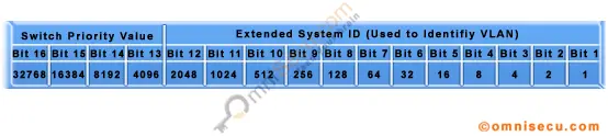
From above image, we can see that Bridge Priority (Switch Priority) Value is represented only by using the left most four bits and the remaining 12 bits are used to represent Extended System ID. If we want to change the Bridge Priority (Switch Priority) Value, the least change is possible only from the 13th bit, which is 2^12.
So what is Spanning Tree Extended System ID? The Extended System ID is utilized by spanning-tree to include the VLAN ID information inside 16-bit STP Bridge Priority value. Extended System ID is the least significant 12-bits in 16-bit STP Bridge Priority value.
Hence the Bridge Priority (Switch Priority) Value 32769 from the output of show command «show spanning-tree» is the sum of default Bridge Priority (Switch Priority) Value 32768 and the VLAN number, 1 (above example, I have only one VLAN).
Do you have any suggestions?
Cisco IOS Show command «show spanning-tree» will show the changed Switch Priority value as below.
omnisecu.com.SW1#show spanning-tree
VLAN0001
Spanning tree enabled protocol ieee
Root ID Priority
Address 000A.F379.A66C
This bridge is the root
Hello Time 2 sec Max Age 20 sec Forward Delay 15 sec
Bridge ID Priority 24577 (priority 24576 sys-id-ext 1)
Address 000A.F379.A66C
Hello Time 2 sec Max Age 20 sec Forward Delay 15 sec
Aging Time 20
Interface Role Sts Cost Prio.Nbr Type
—————- —- — ——— ——— ———————————
Gi1/1 Desg FWD 4 128.25 P2p
Gi1/2 Desg FWD 4 128.26 P2p
In this article we will examine the Spanning Tree Bridge ID structure, explain why it has increments of 4096, how VLAN information is embedded (for Per-VLAN Spanning Tree & multiple STP instances) via the System ID Extension and finally explain how the Spanning Tree Protocol Root Bridge Election occurs.
- Understanding Bridge ID, Bridge Priority & System ID Extension
- The Root Bridge Election Process
- Root Bridge Election Example
- What if we wanted Switch 3 to be the Root Bridge?
- Spanning Tree Configuration (3
- PVST+ Configuration (3
- Catalyst 2960 Default Configuration (3
- Table 3-7 Default Switch Configuration
- Example 3-4 Verifying the Root Bridge and BID
- PortFast and BPDU Guard (3
- Example 3-5 Configuring PortFast
- Example 3-6 Configuring and Verifying BPDU Guard
- PVST+ Load Balancing (3
- Example 3-7 Configuring Primary and Secondary Root Bridges for Each VLAN on S3
- Example 3-8 Configuring Primary and Secondary Root Bridges for Each VLAN on S1
- Example 3-9 Configuring the Lowest Possible Priority to Ensure That a Switch Is Root
Understanding Bridge ID, Bridge Priority & System ID Extension
In our earlier article we discussed about the Spanning Tree Protocol, Rapid STP port costs and port states. Before STP decides which path is the best to the Root Bridge, it needs to first decide which switch has to be elected as the Root Bridge, which is where the Bridge ID comes into play. Readers interested can also read our STP Principles, Redundant Network Links & Broadcast Storms article.
Every switch has an identity when they are part of a network. This identity is called the Bridge ID or BID. It is an 8 byte field which is divided into two parts. The first part is a 2-byte Bridge Priority field (which can be configured) while the second part is the 6-byte MAC address of the switch. While the Bridge Priority is configurable, the MAC address is unique amongst all switches and the sum of these two ensures a unique Bridge ID.
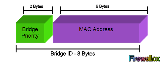
The above Bridge ID assumes there is one Spanning Tree instance for the entire network. This is also called Common Spanning-Tree (CST).
As networks begun to grow and become more complex, VLANs were introduced, allowing the creation of multiple logical and physical networks. It was then necessary to run multiple instances of STP in order to accommodate each network — VLAN. These multiple instances are called Multiple Spanning Tree (MST), Per-VLAN Spanning Tree (PVST) and Per-VLAN Spanning Tree Plus (PVST+).
In order to accommodate the additional VLAN information, the Extended System ID field was introduced, borrowing 12 bits from the original Bridge Priority:
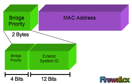
The two values (Bridge Priority + System ID Extension) together make up the Bridge ID used to elect the Root Bridge.
The Root Bridge Election Process
The election process uses several STP messages sent between switches which help each switch to decide, who is the Root Bridge. These messages are called Hello BPDU where BPDU stands for Bridge Protocol Data Unit. It is important to understand the information these BPDUs carry as it will help understand the election process itself.
For the purpose of this exercise, we will only concentrate on the first three fields.
Now, the election process itself is very simple. The switch with the lowest BID becomes the Root Bridge. Since the BID starts with the Bridge Priority field, essentially, the switch with the lowest Bridge Priority field becomes the Root Bridge. If there is a tie between two switches having the same priority value, then the switch with the lowest MAC address becomes the Root Bridge.
The STP Root Bridge election process starts with each switch advertising themselves as the Root Bridge and constructing the Hello BPDU accordingly. So each switch lists its own BID as the Root BID. The Sender Bridge ID is ofcourse the same as the Root BID, as it is again its own BID. With in BPDU, the Cost field is listed with a value of 0, because there is no cost between itself. The switches send out the Hello BPDU constructed as above, onto the network. They will keep on maintaining their status as Root Bridge by default, until they receive a Hello BPDU which carries a lower BID. This Hello BPDU then becomes a superior BPDU. Now the switch receiving this superior BPDU makes changes to the Hello BPDU it has been sending out. It changes the value of the Root BID to reflect the Root BID from the superior Hello BPDU. This process continues till every switch agrees on which switch has the lower BID, and hence deserves to be the Root Bridge.
Root Bridge Election Example
Let’s look at this process using a three switch combination within a network. For the sake of simplicity, the MAC address of each switch has been changed to a simple value:
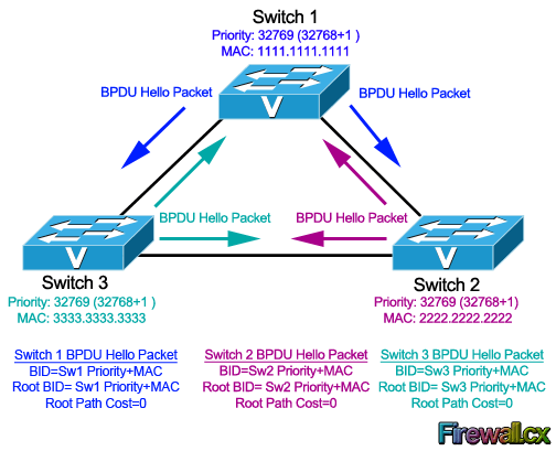
Now, the election process commences with the advertisement of the individual Hello BPDU’s from each switch, as indicated by the arrows in our diagram. These BPDUs originate from each switch and end up at the other switches. Let’s take up one switch at a time to see how it reacts to the BPDUs it receives from the other switches.
Switch 1 (SW1): It had sent out its own Hello BPDU with both BID and Root BID set to 32769.1111.1111.1111. When it receives the Hello BPDU from SW2, it checks for the Root BID value which is 32769.2222.2222.2222. SW1 discards the BPDU sent by SW2, as it still is the switch with the lowest BID. Same situation happens when it receives the Hello BPDU from SW3. SW1 is still the switch with the lowest BID. So it discards the Hello BPDU received from SW3 and keeps on advertising itself as the Root Bridge.
Switch 2 (SW2): Just like SW1, SW2 generates and sends its own Hello BPDU with both BID and Root BID set to 32769.2222.2222.2222. When it receives the Hello BPDU from SW1, it checks for the Root BID value which SW1 has set to 32769.1111.1111.1111. This being lower than SW2’s own BID, makes the Hello BPDU received from SW1, a superior BPDU. So in its own BPDU, SW2 changes the value of the Root BID from 32769.2222.2222.2222, to 32769.1111.1111.1111, and starts advertising this revised Hello BPDU. SW2 now considers SW1 as the Root Bridge. Now, when it receives the Hello BPDU from SW3, it will obviously discard the BPDU as it is not superior in Root BID value. So for SW2, SW1 remains as Root Bridge, even after receiving the Hello BPDU from SW3.
Switch 3 (SW3): SW3 will send out its own Hello BPDU with both BID and Root BID set to 32769.3333.3333.3333. Depending on which Hello BPDU it receives first i.e. from SW1 or SW2, it will end up changing the Root BID value in its Hello BPDU because both SW1 & SW2 have lower MAC addresses. So if it received the Hello BPDU from SW2 first, then it will change the Root BID from 32769.3333.3333.3333 to 32769.2222.2222.2222 and consider SW2 as new Root Bridge. Once it receives the Hello BPDU from SW1, this BPDU supersedes the BPDU sent by SW2. So SW3 changes the Root BID from 32769.2222.2222.2222 to 32769.1111.1111.1111 and now considers SW1 as new Root Bridge.
At this point, all switches have received each other’s BPDU and have agreed that SW1 has the lowerst BID address and is therefore the rightful Root Bridge of the network. Both SW2, and SW3 now agree that SW1 is Root Bridge, and start organizing their respective links into Root Ports and Designated Ports.
What if we wanted Switch 3 to be the Root Bridge?
In most real-life cases, we need to configure the Root Bridge to ensure that no matter the switch that joins the network, our initial Root Bridge will remain. To achieve this, we simply configure the Bridge Priority so that it is always smaller than the default value of 32769.
In our example, if we wanted Switch 3 to become the new Root Bridge, we would set its Bridge Priority to 4096 (4096+1 for VLAN 1). By doing so, we change its BID to 4097.3333.3333.3333 making it the lowest amongst our network switches.
This article analysed the Spanning Tree Protocol Bridge ID structure and its importance. We saw how the Bridge Priority and System ID Extension fields play a primary role in the Root Bridge election within a network.
Back to the Spanning Tree Protocol Section
Spanning Tree Configuration (3
In this section, you will learn how to implement PVST+ and Rapid PVST+ in a switched LAN environment.
PVST+ Configuration (3
The focus of this topic is on how to configure PVST+ in a switched LAN environment.
Catalyst 2960 Default Configuration (3
Table 3-7 shows the default spanning-tree configuration for a Cisco Catalyst 2960 Series switch. Notice that the default spanning-tree mode is PVST+.
Table 3-7 Default Switch Configuration
To ensure that a switch has the lowest bridge priority value, use the spanning-tree vlan vlan-id root primary command in global configuration mode. The priority for the switch is set to the predefined value of 24,576 or to the highest multiple of 4096 less than the lowest bridge priority detected on the network.
If an alternate root bridge is desired, use the spanning-tree vlan vlan-id root secondary global configuration mode command. This command sets the priority for the switch to the predefined value 28,672. This ensures that the alternate switch becomes the root bridge if the primary root bridge fails. This assumes that the rest of the switches in the network have the default 32,768 priority value defined.
In Figure 3-39, S1 has been assigned as the primary root bridge, using the spanning-tree vlan 1 root primary command, and S2 has been configured as the secondary root bridge, using the spanning-tree vlan 1 root secondary command.
Method 2
Another method for configuring the bridge priority value is by using the spanning-tree vlan vlan-id priority value global configuration mode command. This command gives more granular control over the bridge priority value. The priority value is configured in increments of 4096 between 0 and 61,440.
In the example in Figure 3-39, S3 has been assigned a bridge priority value of 24,576, using the spanning-tree vlan 1 priority 24576 command.
To verify the bridge priority of a switch, use the show spanning-tree command. In Example 3-4, the priority of the switch has been set to 24,576. Also notice that the switch is designated as the root bridge for the spanning-tree instance.
Example 3-4 Verifying the Root Bridge and BID
S3# show spanning-tree
VLAN0001
Spanning tree enabled protocol ieee
Root ID Priority 24577
Address 000A.0033.0033
This bridge is the root
Hello Time 2 sec Max Age 20 sec Forward Delay 15 sec
Bridge ID Priority 24577 (priority 24576 sys-id-ext 1)
Address 000A.0033.3333
Hello Time 2 sec Max Age 20 sec Forward Delay 15 sec
Aging Time 300
Interface Role Sts Cost Prio.Nbr Type
——————- —- — ——— ——— ————————
Fa0/1 Desg FWD 4 128.1 P2p
Fa0/2 Desg FWD 4 128.2 P2p
PortFast and BPDU Guard (3
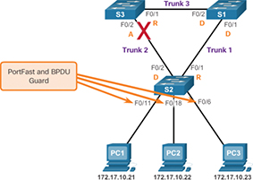
Figure 3-40 PortFast and BPDU Guard Topology
In a valid PortFast configuration, BPDUs should never be received because that would indicate that another bridge or switch is connected to the port, potentially causing a spanning-tree loop. Cisco switches support a feature called BPDU guard. When it is enabled, BPDU guard puts the port in an errdisabled (error-disabled) state on receipt of a BPDU. This effectively shuts down the port. The BPDU guard feature provides a secure response to invalid configurations because you must manually put the interface back into service.
Cisco PortFast technology is useful for DHCP. Without PortFast, a PC can send a DHCP request before the port is in forwarding state, denying the host from getting a usable IP address and other information. Because PortFast immediately changes the state to forwarding, the PC always gets a usable IP address (if the DHCP server has been configured correctly and communication with the DHCP server has occurred).
To configure PortFast on a switch port, enter the spanning-tree portfast interface configuration mode command on each interface on which PortFast is to be enabled, as shown in Example 3-5.
Example 3-5 Configuring PortFast
The spanning-tree portfast default global configuration mode command enables PortFast on all non-trunking interfaces.
To configure BPDU guard on a Layer 2 access port, use the spanning-tree bpduguard enable interface configuration mode command, as shown in Example 3-6.
Example 3-6 Configuring and Verifying BPDU Guard
S2(config-if)# spanning-tree bpduguard enable
S2(config-if)# end
S2#
S2# show running-config interface f0/11
interface FastEthernet0/11
spanning-tree portfast
spanning-tree bpduguard enable
S2#
The spanning-tree portfast bpduguard default global configuration command enables BPDU guard on all PortFast-enabled ports.
Notice in Example 3-6 how the show running-config interface command can be used to verify that PortFast and BPDU guard have been enabled for a switch port. PortFast and BPDU guard are disabled, by default, on all interfaces.
PVST+ Load Balancing (3
The topology in Figure 3-41 shows three switches with 802.1Q trunks connecting them.
In addition to establishing a root bridge, it is also possible to establish a secondary root bridge. A secondary root bridge is a switch that may become the root bridge for a VLAN if the primary root bridge fails. Assuming that the other bridges in the VLAN retain their default STP priority, this switch becomes the root bridge if the primary root bridge fails.
Example 3-7 Configuring Primary and Secondary Root Bridges for Each VLAN on S3
S3(config)# spanning-tree vlan 20 root primary
S3(config)# spanning-tree vlan 10 root secondary
Example 3-8 Configuring Primary and Secondary Root Bridges for Each VLAN on S1
S1(config)# spanning-tree vlan 10 root primary
S1(config)# spanning-tree vlan 20 root secondary
Another way to specify the root bridge is to set the spanning-tree priority on each switch to the lowest value so that the switch is selected as the primary bridge for its associated VLAN, as shown in Example 3-9.
Example 3-9 Configuring the Lowest Possible Priority to Ensure That a Switch Is Root
S3(config)# spanning-tree vlan 20 priority 4096
Switch stacks help maintain or reduce the impact of diameter on STP reconvergence. In a switch stack, all switches use the same bridge ID for a given spanning-tree instance. This means that, if the switches are stacked, as shown in Figure 3-51, the maximum diameter becomes 3 instead of 9.
Redundant links are used to provide a backup path when one link goes down but a Redundant link can sometimes cause switching loops. The main purpose of Spanning Tree Protocol (STP) is to ensure that you do not create loops when you have redundant paths in your network.
Spanning Tree Protocol (STP) – As IEEE STP is used to make a loop-free network by monitoring the network to track all the links and shut down the redundant ones. These are some important terms related to Spanning Tree Protocol:
Designated port – The port which sends the best BPDU i.e ports on the root bridge will be in a forwarding state. Root port – The port which receives the best BPDU on a non-root bridge. Criteria for selecting root port:
(Port priority + Port number) – Port priority is by default 128 and port number is the switch interface number.
Election procedure – All the switches in the network declare themselves root bridges and start exchanging their own BPDU. The BPDU with the lowest bridge ID is considered as superior. Now the switch receiving the superior BPDU makes changes in its own BPDU and carries forward to its neighbours. It changes the value of root Bridge ID with its superior BPDU bridge ID. This process goes on until all the switches are satisfied with which bridge has the lowest bridge ID and hence that switch will be declared as the root bridge.
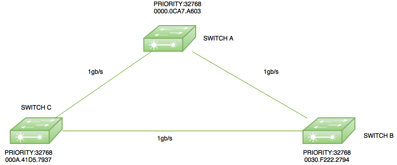
Here is a small topology with three switches switch A (mac address-0000.0ACA7.A603), switch B(0030.F222.2794), and switch C(000A.41D5.7937) with all having default priority (32768).
Root Bridge election – As all the switches have default priority therefore there is a tie on the basis of priority. Now, the switch with the lowest Mac address will become a root bridge. Here, switch A will become the root bridge as it has the lowest Mac address. Therefore, the ports of switch A will be in forwarding state i.e designated port.

Root Ports Election – The root ports are selected on non-root bridges, i.e. switch B and switch C. Now, for instance, if switch C choose the path through switch B then the cost will be (4+4=8) but if it chooses the directly connected path to switch A then the cost will be 4, therefore, both switch B and switch C will choose the ports connected to switch A as their root ports.


