
This section describes specific bridge NAT options.
Sub-menu: /interface bridge nat
Port submenu is used to add interfaces in a particular bridge.
Sub-menu: /interface bridge port
Sub-menu: /interface bridge port mst-override
This section is used to select desired path for each VLAN mapping inside a MSTP region.
MAC addresses that have been learned on a bridge interface can be viewed in the menu. Below is a table of parameters and flags that can be viewed.
Sub-menu: /interface bridge host
Sub-menu: /interface bridge msti
This section is used to group multiple VLAN IDs to a single instance to create a different root bridge for each VLAN group inside a MSTP region.
- Spanning tree incorporated 802.1t, and per 802.1t, uses the 4 most-significant bits of the 802.1d two-octet priority field as priority, and the least-significant 12 bits of that field as the extended system ID.
To get the active hosts table:
[admin@MikroTik] /interface bridge host print
Flags: X - disabled, I - invalid, D - dynamic, L - local, E - external
 #       MAC-ADDRESS        VID ON-INTERFACE            BRIDGE
 0   D   B8:69:F4:C9:EE:D7      ether1                  bridge1
 1   D   B8:69:F4:C9:EE:D8      ether2                  bridge1
 2   DL  CC:2D:E0:E4:B3:38      bridge1                 bridge1
 3   DL  CC:2D:E0:E4:B3:39      ether2                  bridge1
To monitor the current status of a bridge interface, use the
Sub-menu: /interface bridge monitor
[admin@MikroTik] /interface bridge monitor bridge1
                  state: enabled
    current-mac-address: CC:2D:E0:E4:B3:38
            root-bridge: yes
         root-bridge-id: 0x8000.CC:2D:E0:E4:B3:38
         root-path-cost: 0
              root-port: none
             port-count: 2
  designated-port-count: 2          fast-forward: no
- Cisco home page for the Spanning-Tree protocol family (discusses CST, MISTP, PVST, PVST+, RSTP, STP)
- STP article in the Wireshark wiki Includes a sample PCAP-file of captured STP traffic.
- Perlman, Radia. «Algorhyme». University of California at Berkeley. Archived from the original on 2011-07-19.
- IEEE Standards
- RFCs
- Spanning Tree Direct vs Indirect Link Failures — CCIE Study
- Spanning Tree Protocol Overview
To add and enable a bridge interface that will forward L2 packets:
[admin@MikroTik] > interface bridge add
[admin@MikroTik] > interface bridge print
Flags: X - disabled, R - running
0 R name="bridge1" mtu=auto actual-mtu=1500 l2mtu=65535 arp=enabled arp-timeout=auto mac-address=5E:D2:42:95:56:7F protocol-mode=rstp fast-forward=yes
igmp-snooping=no auto-mac=yes ageing-time=5m priority=0x8000 max-message-age=20s forward-delay=15s transmit-hold-count=6 vlan-filtering=no
dhcp-snooping=no
To group ether1 and ether2 in the already created bridge1 interface.
[admin@MikroTik] /interface bridge port add bridge=bridge1 interface=ether1
[admin@MikroTik] /interface bridge port add bridge=bridge1 interface=ether2
[admin@MikroTik] /interface bridge port print
Flags: X - disabled, I - inactive, D - dynamic, H - hw-offload
 #     INTERFACE       BRIDGE       HW  PVID PRIORITY  PATH-COST INTERNAL-PATH-COST    HORIZON
 0     ether1          bridge1      yes  100     0x80         10                 10       none
 1     ether2          bridge1      yes  200     0x80         10                 10       none
Starting from RouterOS version 6.41, the bridge supports IGMP/MLD snooping. It controls multicast streams and prevents multicast flooding on unnecessary ports. Its settings are placed in the bridge menu and it works independently in every bridge interface. Software-driven implementation works on all devices with RouterOS, but CRS3xx, CRS5xx series switches, CCR2116, CR2216 routers, and 88E6393X, 88E6191X, 88E6190 switch chips also support IGMP/MLD snooping with hardware offloading. See more details on IGMP/MLD snooping manual.
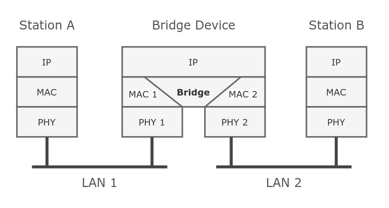
Ethernet-like networks (Ethernet, Ethernet over IP, IEEE 802.11 in ap-bridge or bridge mode, WDS, VLAN) can be connected together using MAC bridges. The bridge feature allows the interconnection of hosts connected to separate LANs (using EoIP, geographically distributed networks can be bridged as well if any kind of IP network interconnection exists between them) as if they were attached to a single LAN. As bridges are transparent, they do not appear in the traceroute list, and no utility can make a distinction between a host working in one LAN and a host working in another LAN if these LANs are bridged (depending on the way the LANs are interconnected, latency and data rate between hosts may vary).
Under the bridge settings menu, it is possible to control certain features for all bridge interfaces and monitor global bridge counters.
Sub-menu: /interface bridge settings
In case you want to assign Simple Queues or global Queue Trees to traffic that is being forwarded by a bridge, then you need to enable the property. Without using this property the bridge traffic will never reach the postrouting chain, Simple Queues and global Queue Trees are working in the postrouting chain. To assign Simple Queues or global Queue Trees for VLAN or PPPoE traffic in a bridge you should enable appropriate properties as well.
The Spanning Tree Protocol (STP) is a network protocol that builds a loop-free logical topology for Ethernet networks. The basic function of STP is to prevent bridge loops and the broadcast radiation that results from them. Spanning tree also allows a network design to include backup links providing fault tolerance if an active link fails.
In 2001, the IEEE introduced Rapid Spanning Tree Protocol (RSTP) as 802.1w. RSTP provides significantly faster recovery in response to network changes or failures, introducing new convergence behaviors and bridge port roles to do this. RSTP was designed to be backwards-compatible with standard STP.
The election process in MSTP can be divided into two sections, intra region and inter region. For MSTP to work properly there will always need to be a regional root, that is the root bridge inside a region, and a CIST root, that is the root bridge between regions. A regional root is the root bridge inside a region, regional root bridge will be needed to properly set up load balancing for VLAN groups inside a region. CIST root will be used to configure which ports will be alternate/backups ports (inactive) and which ports will be root ports (active).
![]()
- The following parameters are involved to elect a regional root bridge or root ports inside a MSTP region:
- The following parameters are involved to elect a CIST root bridge or CIST root ports:
![]()
- VLAN Example — Trunk and Hybrid Ports
- Disadvantages and current practice
- Bridge Packet Filter
- VLAN Example — InterVLAN Routing by Bridge
- Multiple Spanning Tree Protocol
- STP vs. RSTP vs. MSTP
- How Does STP Work?
- Basic Concepts of STP
- STP Implementation
- Spanning Tree Protocol standards
- Rapid Spanning Tree Protocol
- Rapid Spanning Tree operation
- Spanning Tree Protocol
- Interface lists
- Bridge Interface Setup
- Bridge Port Monitoring
- Bridge Hardware Offloading
- Bridge VLAN Filtering
- Why Do We Need STP?
- DHCP Snooping and DHCP Option 82
- Standards for VLANs
- Multiple Spanning Tree Protocol
- Management access configuration
- Untagged access without VLAN filtering
- Tagged access without VLAN filtering
- Tagged access with VLAN filtering
- Untagged access with VLAN filtering
- Changing untagged VLAN for the bridge interface
- Bridge VLAN table
- VLAN Tunneling (QinQ)
- STP and RSTP
- Shortest path bridging
- System ID Extension
- Spanning Tree Protocol
- VLAN Example — Trunk and Access Ports
- Bridge port settings
- Static entries
- Typical Applications of STP
- Bridge protocol data units
- Bridge protocol data unit fields
- Bridge host table
- Static entries
- Controller Bridge and Port Extender
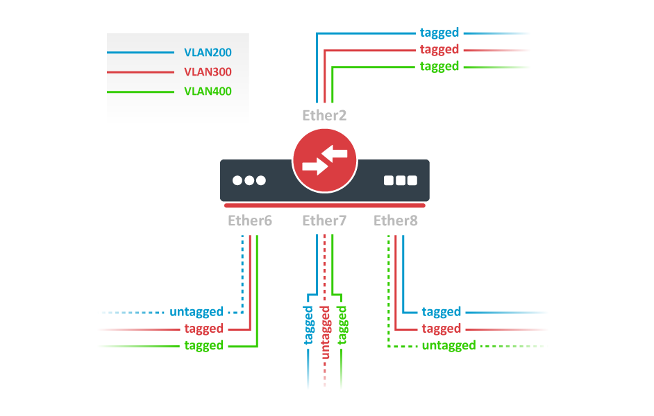
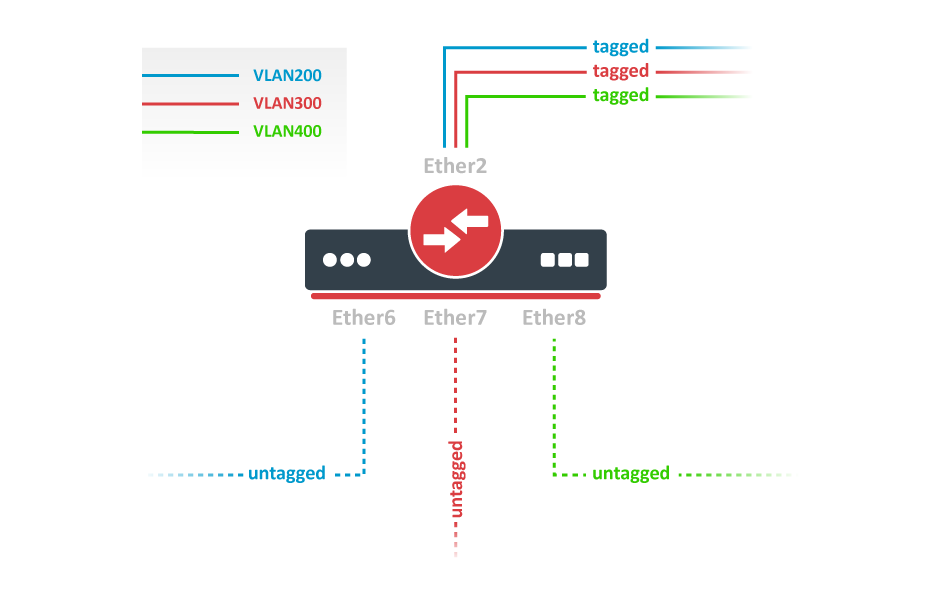
VLAN Example — Trunk and Hybrid Ports
Create a bridge with disabled to avoid losing access to the router before VLANs are completely configured. If you need a management access to the bridge, see the Management access configuration section.
/interface bridge
add name=bridge1 vlan-filtering=no
Add bridge ports and specify on hybrid VLAN ports to assign untagged traffic to the intended VLAN. Use setting to accept only tagged packets on ether2.
/interface bridge port
add bridge=bridge1 interface=ether2 frame-types=admit-only-vlan-tagged
add bridge=bridge1 interface=ether6 pvid=200
add bridge=bridge1 interface=ether7 pvid=300
add bridge=bridge1 interface=ether8 pvid=400
Add Bridge VLAN entries and specify tagged ports in them. In this example egress VLAN tagging is done on ether6,ether7,ether8 ports too, making them into hybrid ports. Bridge ports with will be automatically added as untagged ports for the
/interface bridge vlan
add bridge=bridge1 tagged=ether2,ether7,ether8 vlan-ids=200
add bridge=bridge1 tagged=ether2,ether6,ether8 vlan-ids=300
add bridge=bridge1 tagged=ether2,ether6,ether7 vlan-ids=400
In the end, when VLAN configuration is complete, enable Bridge VLAN Filtering.
/interface bridge set bridge1 vlan-filtering=yes
Optional step is to set on the bridge interface in order to disable the default untagged VLAN 1 ().
/interface bridge set bridge1 frame-types=admit-only-vlan-tagged
You don’t have to add access ports as untagged ports, because they will be added dynamically as an untagged port with the VLAN ID that is specified in, you can specify just the trunk port as a tagged port. All ports that have the sameset will be added as untagged ports in a single entry. You must take into account that the bridge itself is a port and it also has avalue, this means that the bridge port also will be added as an untagged port for the ports that have the same . You can circumvent this behavior by either setting different on all ports (even the trunk port and bridge itself), or to use set to .
Disadvantages and current practice
Configuring connections between network equipment as layer-3 IP links and relying on IP routing for resiliency and to prevent loops is a popular alternative.
Switch virtualization techniques like Cisco Virtual Switching System and Virtual PortChannel and HP Intelligent Resilient Framework combine multiple switches into a single logical entity. Such a multi-chassis link aggregation group works like a normal port trunk, only distributed through multiple switches. Conversely, partitioning technologies compartmentalize a single physical chassis into multiple logical entities.
Bridge Packet Filter
This section describes specific bridge filter options.
Sub-menu: /interface bridge filter
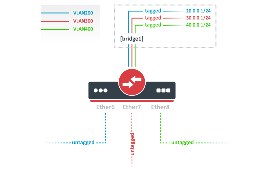
VLAN Example — InterVLAN Routing by Bridge
Create a bridge with disabled to avoid losing access to the router before VLANs are completely configured. If you need a management access to the bridge, see the Management access configuration section.
/interface bridge
add name=bridge1 vlan-filtering=no
Add bridge ports and specify for VLAN access ports to assign their untagged traffic to the intended VLAN. Use setting to accept only untagged packets.
/interface bridge port
add bridge=bridge1 interface=ether6 pvid=200 frame-types=admit-only-untagged-and-priority-tagged
add bridge=bridge1 interface=ether7 pvid=300 frame-types=admit-only-untagged-and-priority-tagged
add bridge=bridge1 interface=ether8 pvid=400 frame-types=admit-only-untagged-and-priority-tagged
Add Bridge VLAN entries and specify tagged ports in them. In this example bridge1 interface is the VLAN trunk that will send traffic further to do InterVLAN routing. Bridge ports with will be automatically added as untagged ports for the
/interface bridge vlan
add bridge=bridge1 tagged=bridge1 vlan-ids=200
add bridge=bridge1 tagged=bridge1 vlan-ids=300
add bridge=bridge1 tagged=bridge1 vlan-ids=400
Configure VLAN interfaces on the bridge1 to allow handling of tagged VLAN traffic at routing level and set IP addresses to ensure routing between VLANs as planned.
/interface vlan
add interface=bridge1 name=VLAN200 vlan-id=200
add interface=bridge1 name=VLAN300 vlan-id=300
add interface=bridge1 name=VLAN400 vlan-id=400
/ip address
add address=20.0.0.1/24 interface=VLAN200
add address=30.0.0.1/24 interface=VLAN300
add address=40.0.0.1/24 interface=VLAN400
In the end, when VLAN configuration is complete, enable Bridge VLAN Filtering:
/interface bridge set bridge1 vlan-filtering=yes
Optional step is to set on the bridge interface in order to disable the default untagged VLAN 1 ().
/interface bridge set bridge1 frame-types=admit-only-vlan-tagged
Since RouterOS v7, it is possible to route traffic using the L3 HW offloading on certain devices. See more details on L3 Hardware Offloading.
Multiple Spanning Tree Protocol
Since RouterOS v6.41 it is possible to enable Multiple Spanning Tree Protocol (MSTP) on a bridge interface to ensure loop-free topology across multiple VLANs, MSTP can also provide Layer2 redundancy and can be used as a load balancing technique for VLANs since it has the ability to have different paths across different VLANs. MSTP is operating very similarly to (R)STP and many concepts from (R)STP can be applied to MSTP and it is highly recommended to understand the principles behind (R)STP before using MSTP, but there are some differences that must be taken into account when designing a MSTP enabled network.
In case (R)STP is used, the BPDUs are sent across all physical interfaces in a bridge to determine loops and stop ports from being able to forward traffic, if it causes a loop. In case there is a loop inside a certain VLAN, (R)STP might not be able to detect it. Some STP variants solve this problem by running a STP instance on every single VLAN (PVST), but this has been proven to inefficient and some STP variants solve this problem by running a single STP instance across all VLANs (CST), but it lacks the possibility to do load balancing for each VLAN or VLAN group. MSTP tends to solve both problems by using MST instances that can define a group of VLANs (VLAN mapping) that can be used for load balancing and redundancy, this means that each VLAN group can have a different root bridge and a different path. Note that it is beneficial to group multiple VLANs in a single instance to reduce the amount of CPU cycles for each network topology change.
![]()
Warning: In RouterOS with MSTP enabled the bridge priority is the CIST’s root bridge priority, as stated in the IEEE 802.1Q standard the bridge priority must be in steps of 4096, the 12 lowest bits are ignored. These are valid bridge priorities: 0, 4096, 8192, 12288, 16384, 20480, 24576, 28672, 32768, 36864, 40960, 45056, 49152, 53248, 57344, 61440. When setting an invalid bridge priority, RouterOS will warn you about it and trunk the value to a valid value, but will save the original value in the configuration since invalid bridge priority values can still be used in (R)STP between devices running RouterOS, though it is recommended to use valid a bridge priority instead.
STP vs. RSTP vs. MSTP
STP can fall into two meanings:
- In a narrow sense, STP refers to the STP protocol defined in IEEE 802.1D.
- In a broad sense, STP refers to the STP protocol defined in IEEE 802.1D, Rapid Spanning Tree Protocol (RSTP) defined in IEEE 802.1w, and Multiple Spanning Tree Protocol (MSTP) defined in IEEE 802.1s.
- STP, a management protocol at the data link layer, is used to detect and prevent loops on a Layer 2 network. It, however, converges the network topology slowly.
- RSTP, an enhancement to STP, allows for rapid network topology convergence. However, both RSTP and STP have a defect, that is, all the VLANs on the same LAN share the same spanning tree. As a result, redundant links cannot be blocked by VLAN, and packets of all VLANs are forwarded alongside the same spanning tree.
- MSTP defines a virtual VLAN mapping table in which VLAN IDs are associated with spanning tree instances. Not only this, MSTP divides a switching network into multiple regions, each of which has multiple spanning tree instances that are mutually independent. Unlike STP and RSTP, MSTP provides multiple redundant paths for data forwarding. In addition, it implements load balancing among VLANs.
MSTP is compatible with RSTP and STP, and RSTP is compatible with STP. Table 1-1 compares the three spanning tree protocols.
Comparison among STP, RSTP, and MSTP
How Does STP Work?
Basic Concepts of STP
Three elements are involved in trimming a ring network into a loop-free tree network: root bridge, root port, and designated port.
Root bridge: There is only one root bridge on the entire STP network. The root bridge is the logical center, but not necessarily the physical center, of the network. Typically, the root bridge should have high performance and be located at a higher layer of the network. When the network topology changes, the root bridge will be re-elected accordingly.
Root port: The root port on an STP-capable device has the smallest path cost to the root bridge and is responsible for forwarding data to the root bridge. Among all STP-capable ports on a device, the port with the smallest root path cost is the root port. An STP-capable device has only one root port, and there is no root port on the root bridge.
Designated port: Table 1-2 describes the designated bridge and designated port.
Designated bridge and designated port
As shown in Figure 1-2, ports AP1 and AP2 reside on Device1, ports BP1 and BP2 reside on Device2, and ports CP1 and CP2 reside on Device3.
Device1 sends configuration BPDUs to Device2 through AP1. Device1 is the designated bridge of Device2, and AP1 is the designated port on Device1.
Device2 and Device3 are connected to the LAN. If Device2 sends configuration BPDUs to the LAN, it is the designated bridge of the LAN, and BP2 is the designated port on Device2.
Designated bridge and designated port

In addition, a device has a bridge ID (BID) and a port on the device has a port ID (PID). A PID is composed of a port priority and a port number. A BID is composed of a bridge priority and a bridge MAC address. On an STP network, the device with the smallest BID is elected as the root bridge.
STP Implementation
- Select the root bridge: During network initialization, every STP-capable device considers itself the root bridge and sets the root bridge ID to its own BID. These devices then exchange configuration BPDUs and compare their root bridge IDs to find the one with the smallest root bridge ID, which will become the root bridge. All the ports on the root bridge are in Forwarding state.
- Select the root port: A device that is not elected as the root bridge selects the port that receives the optimal configuration BPDU as the root port. The root port is in Forwarding state.
- Select the designated port: The device calculates and generates a configuration BPDU for each port based on the configuration BPDU on the root port and path cost of the root port. The device then compares the generated configuration BPDU with the configuration BPDU received on the port.
If the generated configuration BPDU is superior, the port is selected as the designated port and periodically sends the generated configuration BPDU.

STP networking and calculated topology
In Figure 1-3, DeviceA, DeviceB, and DeviceC are deployed on the network, with priorities 0, 1, and 2, respectively. The path costs between DeviceA and DeviceB, DeviceA and DeviceC, and DeviceB and DeviceC are 5, 10, and 4, respectively.
Initial status of each device
Table 1-3 shows the initial status of each device.
Initial status of each device
Topology calculation process and resulting configuration BPDUs
Table 1-4 shows the topology calculation process and resulting configuration BPDUs. The fields that are compared in a configuration BPDU include the root bridge ID, root path cost, sender BID, sender PID.
STP topology calculation process and resulting configuration BPDUs
After the topology becomes stable, the root bridge still sends configuration BPDUs at intervals specified by the Hello timer. Each non-root bridge forwards the received configuration BPDUs through its designated port. When a non-root bridge receives a superior configuration BPDU on a port, it replaces the configuration BPDU on the port with the received configuration BPDU.
Spanning Tree Protocol standards
Rapid Spanning Tree Protocol
Rapid Spanning Tree operation
- Root — A forwarding port that is the best port from non-root bridge to root bridge
- Designated — A forwarding port for every LAN segment
- Alternate — An alternate path to the root bridge. This path is different from using the root port
- Backup — A backup/redundant path to a segment where another bridge port already connects
- Disabled — Not strictly part of STP, a network administrator can manually disable a port
The number of switch port states a port can be in has been reduced to three instead of STP’s original five:
- Discarding — No user data is sent over the port
- Learning — The port is not forwarding frames yet, but is populating its MAC-address-table
- Forwarding — The port is fully operational
RSTP operational details:
- Detection of root switch failure is done in 3 hello times, which is 6 seconds if the default hello times have not been changed.
- Ports may be configured as edge ports if they are attached to a LAN that has no other bridges attached. These edge ports transition directly to the forwarding state. RSTP still continues to monitor the port for BPDUs in case a bridge is connected. RSTP can also be configured to automatically detect edge ports. As soon as the bridge detects a BPDU coming to an edge port, the port becomes a non-edge port.
- RSTP calls the connection between two or more switches as a «link-type» connection. A port that operates in full-duplex mode is assumed to be point-to-point link, whereas a half-duplex port (through a hub) is considered a shared port by default. This automatic link type setting can be overridden by explicit configuration. RSTP improves convergence on point-to-point links by reducing the Max-Age time to 3 times Hello interval, removing the STP listening state, and exchanging a handshake between two switches to quickly transition the port to forwarding state. RSTP does not do anything differently from STP on shared links.
- Unlike in STP, RSTP will respond to BPDUs sent from the direction of the root bridge. An RSTP bridge will propose its spanning tree information to its designated ports. If another RSTP bridge receives this information and determines this is the superior root information, it sets all its other ports to discarding. The bridge may send an agreement to the first bridge confirming its superior spanning tree information. The first bridge, upon receiving this agreement, knows it can rapidly transition that port to the forwarding state bypassing the listening/learning state transition. This essentially creates a cascading effect away from the root bridge where each designated bridge proposes to its neighbors to determine if it can make a rapid transition. This is one of the major elements that allows RSTP to achieve faster convergence times than STP.
- As discussed in the port role details above, RSTP maintains backup details regarding the discarding status of ports. This avoids timeouts if the current forwarding ports were to fail or BPDUs were not received on the root port in a certain interval.
- RSTP will revert to legacy STP on an interface if a legacy version of an STP BPDU is detected on that port.
Spanning Tree Protocol
RouterOS bridge interfaces are capable of running Spanning Tree Protocol to ensure a loop-free and redundant topology. For small networks with just 2 bridges STP does not bring many benefits, but for larger networks properly configured STP is very crucial, leaving STP-related values to default may result in a completely unreachable network in case of an even single bridge failure. To achieve a proper loop-free and redundant topology, it is necessary to properly set bridge priorities, port path costs, and port priorities.
In RouterOS it is possible to set any value for bridge priority between 0 and 65535, the IEEE 802.1W standard states that the bridge priority must be in steps of 4096. This can cause incompatibility issues between devices that do not support such values. To avoid compatibility issues, it is recommended to use only these priorities: 0, 4096, 8192, 12288, 16384, 20480, 24576, 28672, 32768, 36864, 40960, 45056, 49152, 53248, 57344, 61440
STP has multiple variants, currently, RouterOS supports STP, RSTP, and MSTP. Depending on needs, either one of them can be used, some devices are able to run some of these protocols using hardware offloading, detailed information about which device support it can be found in the Hardware Offloading section. STP is considered to be outdated and slow, it has been almost entirely replaced in all network topologies by RSTP, which is backward compatible with STP. For network topologies that depend on VLANs, it is recommended to use MSTP since it is a VLAN aware protocol and gives the ability to do load balancing per VLAN groups. There are a lot of considerations that should be made when designing an STP enabled network, more detailed case studies can be found in the Spanning Tree Protocol article. In RouterOS, the property controls the used STP variant.
By the IEEE 802.1ad standard, the BPDUs from bridges that comply with IEEE 802.1Q are not compatible with IEEE 802.1ad bridges, this means that the same bridge VLAN protocol should be used across all bridges in a single Layer2 domain, otherwise (R/M)STP will not function properly.
Interface lists
Starting with RouterOS v6.41 it possible to add interface lists as a bridge port and sort them. Interface lists are useful for creating simpler firewall rules. Below is an example how to add an interface list to a bridge:
/interface list
add name=LAN1
add name=LAN2
/interface list member
add interface=ether1 list=LAN1
add interface=ether2 list=LAN1
add interface=ether3 list=LAN2
add interface=ether4 list=LAN2
/interface bridge port
add bridge=bridge1 interface=LAN1
add bridge=bridge1 interface=LAN2
Ports from an interface list added to a bridge will show up as dynamic ports:
[admin@MikroTik] /interface bridge port> pr
Flags: X - disabled, I - inactive, D - dynamic, H - hw-offload
 #     INTERFACE       BRIDGE       HW  PVID PRIORITY  PATH-COST INTERNAL-PATH-COST    HORIZON
 0     LAN1            bridge1      yes    1     0x80         10                 10       none
 1  D  ether1          bridge1      yes    1     0x80         10                 10       none
 2  D  ether2          bridge1      yes    1     0x80         10                 10       none
 3     LAN2            bridge1      yes    1     0x80         10                 10       none
 4  D  ether3          bridge1      yes    1     0x80         10                 10       none
 5  D  ether4          bridge1      yes    1     0x80         10                 10       none
It is also possible to sort the order of lists in which they appear. This can be done using the command. Below is an example of how to sort interface lists:
[admin@MikroTik] > /interface bridge port move 3 0
[admin@MikroTik] > /interface bridge port print
Flags: X - disabled, I - inactive, D - dynamic, H - hw-offload
 #     INTERFACE       BRIDGE       HW  PVID PRIORITY  PATH-COST INTERNAL-PATH-COST    HORIZON
 0     LAN2            bridge1      yes    1     0x80         10                 10       none
 1  D  ether3          bridge1      yes    1     0x80         10                 10       none
 2  D  ether4          bridge1      yes    1     0x80         10                 10       none
 3     LAN1            bridge1      yes    1     0x80         10                 10       none
 4  D  ether1          bridge1      yes    1     0x80         10                 10       none
 5  D  ether2          bridge1      yes    1     0x80         10                 10       none
The second parameter when moving interface lists is considered as «before id», the second parameter specifies before which interface list should be the selected interface list moved. When moving the first interface list in place of the second interface list, then the command will have no effect since the first list will be moved before the second list, which is the current state either way.
Bridge Interface Setup
Changing certain properties can cause the bridge to temporarily disable all ports. This must be taken into account whenever changing such properties on production environments since it can cause all packets to be temporarily dropped. Such properties include , , , and others.
Bridge Port Monitoring
To monitor the current status of bridge ports, use the command.
Sub-menu: /interface bridge port monitor
[admin@MikroTik] /interface bridge port monitor [find interface=ether1]
            interface: ether1
               status: in-bridge
          port-number: 1
                 role: designated-port
            edge-port: yes
  edge-port-discovery: yes
  point-to-point-port: yes
         external-fdb: no
         sending-rstp: yes
             learning: yes
           forwarding: yes
Bridge Hardware Offloading
Since RouterOS v6.41 it is possible to switch multiple ports together if a device has a built-in switch chip. While a bridge is a software feature that will consume CPU’s resources, the bridge hardware offloading feature will allow you to use the built-in switch chip to forward packets, this allows you to achieve higher throughput if configured correctly.
In previous versions (prior to RouterOS v6.41) you had to use the master-port property to switch multiple ports together, but in RouterOS v6.41 this property is replaced with the bridge hardware offloading feature, which allows your to switch ports and use some of the bridge features, for example, Spanning Tree Protocol.
When upgrading from previous versions (before RouterOS v6.41), the old master-port configuration is automatically converted to the new Bridge Hardware Offloading configuration. When downgrading from newer versions (RouterOS v6.41 and newer) to older versions (before RouterOS v6.41) the configuration is not converted back, a bridge without hardware offloading will exist instead, in such a case you need to reconfigure your device to use the old master-port configuration.
Below is a list of devices and feature that supports hardware offloading (+) or disables hardware offloading (-):
- The feature will not work properly in VLAN switching setups. It is possible to correctly snoop DHCP packets only for a single VLAN, but this requires that these DHCP messages get tagged with the correct VLAN tag using an ACL rule, for example,
/interface ethernet switch acl add dst-l3-port=67-68 ip-protocol=udp mac-protocol=ip new-customer-vid=10 src-ports=switch1-cpu. DHCP Option 82 will not contain any information regarding VLAN-ID. - The feature will not work properly in VLAN switching setups.
- The HW vlan-filtering and R/M/STP was added in the RouterOS 7.1rc1 (for RTL8367) and 7.1rc5 (for MT7621) versions. The switch does not support other 0x88a8 or 0x9100 (only 0x8100 is supported) and no
. Using these features will disable HW offload. - The HW offloading will be disabled only for the specific bridge port, not the entire bridge.
- Only 802.3ad and balance-xor modes can be HW offloaded. Other bonding modes do not support HW offloading.
- Currently, HW offloaded bridge support for the IPQ-PPE switch chip is still a work in progress. We recommend using, the default, non-HW offloaded bridge (enabled RSTP).
- The 802.3ad mode compatible only with R/M/STP enabled on the bridge.
When upgrading from older versions (before RouterOS v6.41), only the master-port configuration is converted. For each master-port a bridge will be created. VLAN configuration is not converted and should not be changed, check the Basic VLAN switching guide to be sure how VLAN switching should be configured for your device.
Bridge Hardware Offloading should be considered as port switching, but with more possible features. By enabling hardware offloading you are allowing a built-in switch chip to process packets using its switching logic. The diagram below illustrates that switching occurs before any software related action.
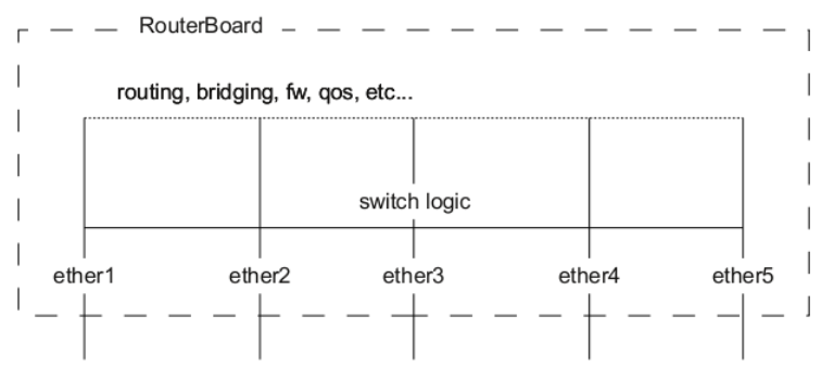
A packet that is received by one of the ports always passes through the switch logic first. Switch logic decides which ports the packet should be going to (most commonly this decision is made based on the destination MAC address of a packet, but there might be other criteria that might be involved based on the packet and the configuration). In most cases the packet will not be visible to RouterOS (only statistics will show that a packet has passed through), this is because the packet was already processed by the switch chip and never reached the CPU.
Though it is possible in certain situations to allow a packet to be processed by the CPU, this is usually called a packet forwarding to the switch CPU port (or the bridge interface in bridge VLAN filtering scenario). This allows the CPU to process the packet and lets the CPU to forward the packet. Passing the packet to the CPU port will give you the opportunity to route packets to different networks, perform traffic control and other software related packet processing actions. To allow a packet to be processed by the CPU, you need to make certain configuration changes depending on your needs and on the device you are using (most commonly passing packets to the CPU are required for VLAN filtering setups). Check the manual page for your specific device:
Certain bridge and Ethernet port properties are directly related to switch chip settings, changing such properties can trigger a switch chip reset, that will temporarily disable all Ethernet ports that are on the switch chip for the settings to have an effect, this must be taken into account whenever changing properties on production environments. Such properties are DHCP Snooping, IGMP Snooping, VLAN filtering, L2MTU, Flow Control, and others (exact settings that can trigger a switch chip reset depends on the device’s model).
The CRS1xx/2xx series switches support multiple hardware offloaded bridges per switch chip. All other devices support only one hardware offloaded bridge per switch chip. Use the hw=yes/no parameter to select which bridge will use hardware offloading.
Bridge VLAN Filtering
Bridge VLAN Filtering since RouterOS v6.41 provides VLAN aware Layer2 forwarding and VLAN tag modifications within the bridge. This set of features makes bridge operation more like a traditional Ethernet switch and allows to overcome Spanning Tree compatibility issues compared to the configuration when VLAN interfaces are bridged. Bridge VLAN Filtering configuration is highly recommended to comply with STP (IEEE 802.1D), RSTP (IEEE 802.1W) standards, and is mandatory to enable MSTP (IEEE 802.1s) support in RouterOS.
Currently, CRS3xx, CRS5xx series switches, CCR2116, CCR2216 routers and RTL8367, 88E6393X, 88E6191X, 88E6190, MT7621 and MT7531 switch chips (since RouterOS v7) are capable of using bridge VLAN filtering and hardware offloading at the same time, other devices will not be able to use the benefits of a built-in switch chip when bridge VLAN filtering is enabled. Other devices should be configured according to the method described in the Basic VLAN switching guide. If an improper configuration method is used, your device can cause throughput issues in your network.
Why Do We Need STP?
Devices on a LAN are often interconnected using redundant links to improve service resilience. This configuration, however, is prone to loops. Loops can easily cause broadcast storms, which can consume sufficient network resources so as to break down the network. Loops can also cause MAC address flapping, damaging the MAC address entries.
DHCP Snooping and DHCP Option 82
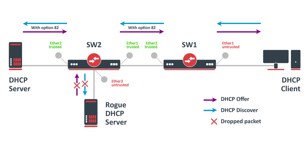
In this example, SW1 and SW2 are DHCP Snooping, and Option 82 enabled devices. First, we need to create a bridge, assign interfaces and mark trusted ports. Use these commands on SW1:
/interface bridge
add name=bridge
/interface bridge port
add bridge=bridge interface=ether1
add bridge=bridge interface=ether2 trusted=yes
For SW2, the configuration will be similar, but we also need to mark ether1 as trusted, because this interface is going to receive DHCP messages with Option 82 already added. You need to mark all ports as trusted if they are going to receive DHCP messages with added Option 82, otherwise these messages will be dropped. Also, we add ether3 to the same bridge and leave this port untrusted, imagine there is an unauthorized (rogue) DHCP server. Use these commands on SW2
/interface bridge
add name=bridge
/interface bridge port
add bridge=bridge interface=ether1 trusted=yes
add bridge=bridge interface=ether2 trusted=yes
add bridge=bridge interface=ether3
Then we need to enable DHCP Snooping and Option 82. In case your DHCP server does not support DHCP Option 82 or you do not implement any Option 82 related policies, this option can be disabled. Use these commands on SW1 SW2
/interface bridge
set [find where name="bridge"] dhcp-snooping=yes add-dhcp-option82=yes
Now both devices will analyze what DHCP messages are received on bridge ports. The SW1 is responsible for adding and removing the DHCP Option 82. The SW2 will limit rogue DHCP server from receiving any discovery messages and drop malicious DHCP server messages from ether3.
Currently, CRS3xx, CRS5xx series switches, CCR2116, CR2216 routers, and 88E6393X, 88E6191X, 88E6190 switch chips fully support hardware offloaded DHCP Snooping and Option 82. For CRS1xx and CRS2xx series switches it is possible to use DHCP Snooping along with VLAN switching, but then you need to make sure that DHCP packets are sent out with the correct VLAN tag using egress ACL rules. Other devices are capable of using DHCP Snooping and Option 82 features along with hardware offloading, but you must make sure that there is no VLAN-related configuration applied on the device, otherwise, DHCP Snooping and Option 82 might not work properly. SeeBridge Hardware Offloading section with supported features.
For CRS3xx, CRS5xx series switches and CCR2116, CR2216 routers DHCP snooping will not work when hardware offloading bonding interfaces are created.
Standards for VLANs
- VSTP supports only 253 different spanning-tree topologies. If there are more than 253 VLANs, it is recommended to configure RSTP in addition to VSTP, and VLANs beyond 253 will be handled by RSTP.
- MVRP does not support VSTP. If this protocol is in use, VLAN membership for trunk interfaces must be statically configured.[25]
Multiple Spanning Tree Protocol
The Multiple Spanning Tree Protocol (MSTP), originally defined in IEEE 802.1s-2002 and later merged into IEEE 802.1Q-2005, defines an extension to RSTP to further develop the usefulness of VLANs.
MSTP is fully compatible with RSTP bridges in that an MSTP BPDU can be interpreted by an RSTP bridge as an RSTP BPDU. This not only allows compatibility with RSTP bridges without configuration changes but also causes any RSTP bridges outside of an MSTP region to see the region as a single RSTP bridge regardless of the number of MSTP bridges inside the region itself. In order to further facilitate this view of an MSTP region as a single RSTP bridge, the MSTP protocol uses a variable known as remaining hops as a time to live counter instead of the message age timer used by RSTP. The message age time is only incremented once when spanning-tree information enters an MST region, and therefore RSTP bridges will see a region as only one hop in the spanning tree. Ports at the edge of an MSTP region connected to either an RSTP or STP bridge or an endpoint are known as boundary ports. As in RSTP, these ports can be configured as edge ports to facilitate rapid changes to the forwarding state when connected to endpoints.
Management access configuration
There are multiple ways to set up management access on a device that uses bridge VLAN filtering. Below are some of the most popular approaches to properly enable access to a router/switch. Start by creating a bridge without VLAN filtering enabled:
/interface bridge
add name=bridge1 vlan-filtering=no
Untagged access without VLAN filtering
In case VLAN filtering will not be used and access with untagged traffic is desired, the only requirement is to create an IP address on the bridge interface.
/ip address
add address=192.168.99.1/24 interface=bridge1
Tagged access without VLAN filtering
In case VLAN filtering will not be used and access with tagged traffic is desired, create a routable VLAN interface on the bridge and add an IP address on the VLAN interface.
/interface vlan
add interface=bridge1 name=MGMT vlan-id=99
/ip address
add address=192.168.99.1/24 interface=MGMT
Tagged access with VLAN filtering
In case VLAN filtering is used and access with tagged traffic is desired, additional steps are required. In this example, VLAN 99 will be used to access the device. A VLAN interface on the bridge must be created and an IP address must be assigned to it.
/interface vlan
add interface=bridge1 name=MGMT vlan-id=99
/ip address
add address=192.168.99.1/24 interface=MGMT
For example, if you want to allow access to the device from ports ether3, ether4, sfp-sfpplus1 using tagged VLAN 99 traffic, then you must add this entry to the VLAN table. Note that the bridge1 interface is also included in the tagged port list:
/interface bridge vlan
add bridge=bridge1 tagged=bridge1,ether3,ether4,sfp-sfpplus1 vlan-ids=99
After that you can enable VLAN filtering:
/interface bridge set bridge1 vlan-filtering=yes
Untagged access with VLAN filtering
In case VLAN filtering is used and access with untagged traffic is desired, the VLAN interface must use the same VLAN ID as the untagged port VLAN ID (). Just like in the previous example, start by creating a VLAN interface on the bridge and add an IP address for the VLAN.
/interface vlan
add interface=bridge1 name=MGMT vlan-id=99
/ip address
add address=192.168.99.1/24 interface=MGMT
For example, untagged ports ether2 and ether3 should be able to communicate with the VLAN 99 interface using untagged traffic. In order to achieve this, these ports should be configured with the that matches the VLAN ID on management VLAN. Note that the bridge1 interface is a tagged port member, you can configure additional tagged ports if necessary (see the previous example).
/interface bridge port
set [find interface=ether2] pvid=99
set [find interface=ether3] pvid=99
/interface bridge vlan
add bridge=bridge1 tagged=bridge1 untagged=ether2,ether3 vlan-ids=99
After that you can enable VLAN filtering:
/interface bridge set bridge1 vlan-filtering=yes
Changing untagged VLAN for the bridge interface
In case VLAN filtering is used, it is possible to change the untagged VLAN ID for the bridge interface using the setting. Note that creating routable VLAN interfaces and allowing tagged traffic on the bridge is a more flexible and generally recommended option.
First, create an IP address on the bridge interface.
/ip address
add address=192.168.99.1/24 interface=bridge1
For example, untagged bridge1 traffic should be able to communicate with untagged ether2 and ether3 ports and tagged sfp-sfpplus1 port in VLAN 99. In order to achieve this, bridge1, ether2, ether3 should be configured with the same and sfp-sfpplus1 added as a tagged member.
/interface bridge
set [find name=bridge1] pvid=99
/interface bridge port
set [find interface=ether2] pvid=99
set [find interface=ether3] pvid=99
/interface bridge vlan
add bridge=bridge1 tagged=sfp-sfpplus1 untagged=bridge1,ether2,ether3 vlan-ids=99
After that you can enable VLAN filtering:
/interface bridge set bridge1 vlan-filtering=yes
If the connection to the router/switch through an IP address is not required, then steps adding an IP address can be skipped since a connection to the router/switch through Layer2 protocols (e.g. MAC-telnet) will be working either way.
Bridge VLAN table
Bridge VLAN table represents per-VLAN port mapping with an egress VLAN tag action.ports send out frames with a corresponding VLAN ID tag.ports remove a VLAN tag before sending out frames. Bridge ports with set to or will be automatically added as untagged ports for the VLAN.
Sub-menu: /interface bridge vlan
The parameter can be used to specify a set or range of VLANs, but specifying multiple VLANs in a single bridge VLAN table entry should only be used for ports that are tagged ports. In case multiple VLANs are specified for access ports, then tagged packets might get sent out as untagged packets through the wrong access port, regardless of the PVID value.
Make sure you have added all needed interfaces to the bridge VLAN table when using bridge VLAN filtering. For routing functions to work properly on the same device through ports that use bridge VLAN filtering, you will need to allow access to the bridge interface (this automatically include a switch-cpu port when HW offloaded vlan-filtering is used, e.g. on CRS3xx series switches), this can be done by adding the bridge interface itself to the VLAN table, for tagged traffic you will need to add the bridge interface as a tagged port and create a VLAN interface on the bridge interface. Examples can be found in the inter-VLAN routing and Management port sections.
When allowing access to the CPU, you are allowing access from a certain port to the actual router/switch, this is not always desirable. Make sure you implement proper firewall filter rules to secure your device when access to the CPU is allowed from a certain VLAN ID and port, use firewall filter rules to allow access to only certain services.
Improperly configured bridge VLAN filtering can cause security issues, make sure you fully understand how Bridge VLAN table works before deploying your device into production environments.
VLAN Tunneling (QinQ)
Since RouterOS v6.43 the RouterOS bridge is IEEE 802.1ad compliant and it is possible to filter VLAN IDs based on Service VLAN ID (0x88A8) rather than Customer VLAN ID (0x8100). The same principles can be applied as with IEEE 802.1Q VLAN filtering (the same setup examples can be used). Below is a topology for a common Provider bridge:
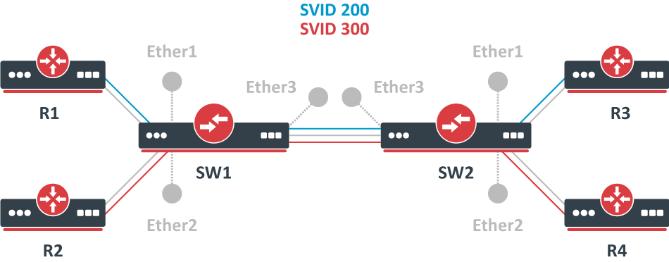
In this example, R1, R2, R3, and R4 might be sending any VLAN tagged traffic by 802.1Q (CVID), but SW1 and SW2 needs isolate traffic between routers in a way that R1 is able to communicate only with R3, and R2 is only able to communicate with R4. To do so, you can tag all ingress traffic with an SVID and only allow these VLANs on certain ports. Start by enabling VLAN protocol on the bridge, use these commands on SW1 and SW2:
/interface bridge
add name=bridge1 vlan-filtering=no ether-type=0x88a8
In this setup, ether1 ether2 are going to be access ports (untagged), use the parameter to tag all ingress traffic on each port, use these commands on SW1 SW2
/interface bridge port
add interface=ether1 bridge=bridge1 pvid=200
add interface=ether2 bridge=bridge1 pvid=300
add interface=ether3 bridge=bridge1
Specify tagged and untagged ports in the bridge VLAN table, use these commands on SW1 SW2
/interface bridge vlan
add bridge=bridge1 tagged=ether3 untagged=ether1 vlan-ids=200
add bridge=bridge1 tagged=ether3 untagged=ether2 vlan-ids=300
When the bridge VLAN table is configured, you can enable bridge VLAN filtering, use these commands on SW1 SW2:
/interface bridge set bridge1 vlan-filtering=yes
By enabling vlan-filtering you will be filtering out traffic destined to the CPU, before enabling VLAN filtering you should make sure that you set up a Management port. The difference between using different EtherTypes is that you must use a Service VLAN interface. Service VLAN interfaces can be created as a regular VLAN interface, but the parameter toggles if the interface will use the Service VLAN tag.
When is configured, the bridge checks the outer VLAN tag and sees if it is using EtherType 0x8100. If the bridge receives a packet with an outer tag that has a different EtherType, it will mark the packet as untagged. Since RouterOS only checks the outer tag of a packet, it is not possible to filter 802.1Q packets when the 802.1ad protocol is used.
Currently, CRS3xx, CRS5xx series switches and CCR2116, CCR2216 routers are capable of hardware offloading VLAN filtering based on SVID (Service VLAN ID) tag when is set to .
Devices with switch chip Marvell-98DX3257 (e.g. CRS354 series) do not support VLAN filtering on 1Gbps Ethernet interfaces for other VLAN types ( and ).
Since RouterOS v6.43 it is possible to forcefully add a new VLAN tag over any existing VLAN tags, this feature can be used to achieve a CVID stacking setup, where a CVID (0x8100) tag is added before an existing CVID tag. This type of setup is very similar toProvider bridge setup, to achieve the same setup but with multiple CVID tags (CVID stacking) we can use the same topology:
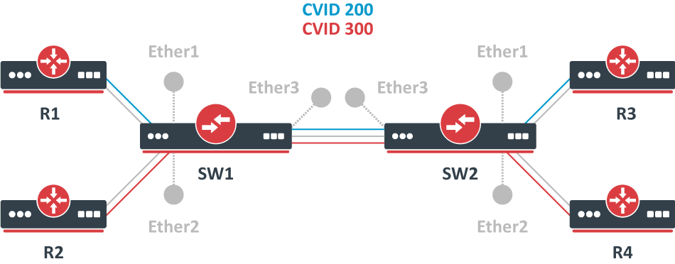
In this example R1, R2, R3, and R4 might be sending any VLAN tagged traffic, it can be 802.1ad, 802.1Q or any other type of traffic, but SW1 and SW2 needs isolate traffic between routers in a way that R1 is able to communicate only with R3, and R2 is only able to communicate with R4. To do so, you can tag all ingress traffic with a new CVID tag and only allow these VLANs on certain ports. Start by selecting the proper EtherType, use these commands on SW1 and SW2:
/interface bridge
add name=bridge1 vlan-filtering=no ether-type=0x8100
In this setup, ether1 ether2 will ignore any VLAN tags that are present and add a new VLAN tag, use the parameter to tag all ingress traffic on each port and allow on these ports, use these commands on SW1 SW2
/interface bridge port
add interface=ether1 bridge=bridge1 pvid=200 tag-stacking=yes
add interface=ether2 bridge=bridge1 pvid=300 tag-stacking=yes
add interface=ether3 bridge=bridge1
Specify tagged and untagged ports in the bridge VLAN table, you only need to specify the VLAN ID of the outer tag, use these commands on SW1 SW2
/interface bridge vlan
add bridge=bridge1 tagged=ether3 untagged=ether1 vlan-ids=200
add bridge=bridge1 tagged=ether3 untagged=ether2 vlan-ids=300
When the bridge VLAN table is configured, you can enable bridge VLAN filtering, which is required in order for the parameter to have any effect, use these commands on SW1 and SW2:
/interface bridge set bridge1 vlan-filtering=yes
By enabling vlan-filtering you will be filtering out traffic destined to the CPU, before enabling VLAN filtering you should make sure that you set up a Management port.
STP and RSTP
STP and Rapid STP are used very widely across many networks, but almost all networks have switched over using only RSTP since of its benefits. STP is a very old protocol and has a convergence time (the time needed to fully learn network topology changes and to continue properly forwarding traffic) even up to 50 seconds, which was acceptable for the 1980s when it was invented. RSTP has a lot of smaller convergence time, a few seconds or even a few milliseconds), which is acceptable for nowadays network requirements. It is recommended to use RSTP instead of STP since it is a lot faster and is also backward compatible with STP. One of the reasons why RSTP is faster is because of reduced possible port states, below is a list of possible STP port states:
- Forwarding — port participates in traffic forwarding and is learning MAC addresses, is receiving BPDUs.
- Listening — port does not participate in traffic forwarding and is not learning MAC addresses, is receiving BPDUs.
- Learning — port does not participate in traffic forwarding but is learning MAC addresses.
- Blocking — port is blocked since it is causing loops but is receiving BPDUs.
- Disabled — port is disabled or inactive.
- Forwarding — port participates in traffic forwarding and is learning MAC addresses, is receiving BPDUs (forwarding=yes).
- Learning — port does not participate in traffic forwarding but is learning MAC addresses (learning=yes).
- Discarding — port does not participate in traffic forwarding and is not learning MAC addresses, is receiving BPDUs (forwarding=no).
In STP connectivity between bridges is determined by sending and receiving BPDUs between neighbor bridges. Designated ports are sending BPDUs to root ports. If a BPDU is not received 3 times the HelloTime in a row, then the connection is considered as unavailable and network topology convergence will commence. It is possible for STP to reduce the convergence time in certain scenarios by reducing the forward-delay timer, which is responsible for how long can the port be in the learning/listening state.
In RouterOS, it is possible to specify which bridge ports are edge ports. Edge ports are ports that are not supposed to receive any BPDUs, this is beneficial since this allows STP to skip the learning and the listening state and directly go to the forwarding state. This feature is sometimes called PortFast· You can leave this parameter to the default value, which is auto, but you can also manually specify it, you can set a port as edge port manually for ports that should not have any more bridges behind it, usually these are access ports.
Shortest path bridging
System ID Extension
The bridge ID (BID) is a field inside a BPDU packet. It is eight bytes in length. The first two bytes are the bridge priority, an unsigned integer of 0–65,535. The last six bytes are a MAC address supplied by the bridge. Prior to IEEE 802.1D-2004, the first two bytes gave a 16-bit bridge priority. Since IEEE 802.1D-2004, the first four bits are a configurable priority, and the last twelve bits carry the bridge system ID extension. In the case of MST, the bridge system ID extension carries the MSTP instance number. Some vendors set the bridge system ID extension to carry a VLAN ID allowing a different spanning tree per VLAN, such as Cisco’s PVST.
Spanning Tree Protocol
RouterOS is capable of running bridge interfaces with (R/M)STP support in order to create a loop-free and Layer2 redundant environment. It is always recommended to manually set up each bridge’s priority, port priority, and port path cost to ensure proper Layer2 functionality at all times. Leaving STP related values to defaults are acceptable for a network that consists of 1 to 2 bridges running with (R/M)STP enabled, but it is highly recommended to manually set these values for larger networks. Since STP elects a root bridge and root ports by checking STP related values from bridges over the network, then leaving STP settings to automatic may elect an undesired root bridge and root ports and in case of a hardware failure can result in an inaccessible network.
You can check the STP status of a bridge by using the /interface bridge monitor command, for example:
/interface bridge monitor bridge state: enabled current-mac-address: 64:D1:54:D9:27:E6 root-bridge: yes root-bridge-id: 0x3000.64:D1:54:D9:27:E6 root-path-cost: 0 root-port: none port-count: 5 designated-port-count: 5
You can check the STP status of a bridge port by using the /interface bridge port monitor command, for example:
/interface bridge port monitor 2 interface: ether3 status: in-bridge port-number: 3 role: root-port edge-port: no edge-port-discovery: yes point-to-point-port: yes external-fdb: no sending-rstp: yes learning: yes forwarding: yes root-path-cost: 10 designated-bridge: 0x3000.64:D1:54:D9:27:E6 designated-cost: 0 designated-port-number: 4 hw-offload-group: switch1
Note that root-bridge-id consists of the bridge priority and the bridge’s MAC address, for non-root bridges the root bridge will be shown as designated-bridge. One port can have one role in an STP enabled network, below is a list of possible port roles:
- root-port — port that is facing towards the root bridge and will be used to forward traffic from/to the root bridge.
- alternate-port — port that is facing towards root bridge, but is not going to forward traffic (a backup for root port).
- backup-port — port that is facing away from the root bridge, but is not going to forward traffic (a backup for non-root port).
- designated-port — port that is facing away from the root bridge and is going to forward traffic.
- disabled-port — disabled or inactive port.
![]()
Note: When using bridges that are set to use 802.1Q as EtherType, they will send out BPDUs to 01:80:C2:00:00:00, which are used by MSTP, RSTP and STP. When using 802.1ad as bridge VLAN protocol, the BPDUs are not compatible with 802.1Q bridges and they are sent to 01:80:C2:00:00:08. (R/M)STP will not function properly if there are different bridge VLAN protocols across the Layer2 network.
VLAN Example — Trunk and Access Ports
Create a bridge with disabled to avoid losing access to the device before VLANs are completely configured. If you need a management access to the bridge, see the Management access configuration section.
/interface bridge
add name=bridge1 vlan-filtering=no
Add bridge ports and specify for access ports to assign their untagged traffic to the intended VLAN. Use setting to accept only tagged or untagged packets.
/interface bridge port
add bridge=bridge1 interface=ether2 frame-types=admit-only-vlan-tagged
add bridge=bridge1 interface=ether6 pvid=200 frame-types=admit-only-untagged-and-priority-tagged
add bridge=bridge1 interface=ether7 pvid=300 frame-types=admit-only-untagged-and-priority-tagged
add bridge=bridge1 interface=ether8 pvid=400 frame-types=admit-only-untagged-and-priority-tagged
Add Bridge VLAN entries and specify tagged ports in them. Bridge ports with will be automatically added as untagged ports for the
/interface bridge vlan
add bridge=bridge1 tagged=ether2 vlan-ids=200
add bridge=bridge1 tagged=ether2 vlan-ids=300
add bridge=bridge1 tagged=ether2 vlan-ids=400
In the end, when VLAN configuration is complete, enable Bridge VLAN Filtering.
/interface bridge set bridge1 vlan-filtering=yes
Optional step is to set on the bridge interface in order to disable the default untagged VLAN 1 ().
/interface bridge set bridge1 frame-types=admit-only-vlan-tagged
Bridge port settings
Each bridge port have multiple VLAN related settings, that can change untagged VLAN membership, VLAN tagging/untagging behavior and packet filtering based on VLAN tag presence.
Sub-menu: /interface bridge port
Static entries
Since RouterOS version 7.7, it is possible to create static MDB entries for IPv4 and IPv6 multicast groups.
Sub-menu: /interface bridge mdb
For example, to create a static MDB entry for multicast group 229.10.10.10 on ports ether2 and ether3 on VLAN 10, use the command below:
/interface bridge mdb
add bridge=bridge1 group=229.10.10.10 ports=ether2,ether3 vid=10
Verify the results with the command:
[admin@MikroTik] > /interface bridge mdb print where group=229.10.10.10
Columns: GROUP, VID, ON-PORTS, BRIDGE # GROUP VID ON-PORTS BRIDGE
12 229.10.10.10 10 ether2 bridge1 ether3
In case a certain IPv6 multicast group does not need to be snooped and it is desired to be flooded on all ports and VLANs, it is possible to create a static MDB entry on all VLANs and ports, including the bridge interface itself. Use the command below to create a static MDB entry for multicast group ff02::2 on all VLANs and ports (modify the setting for your particular setup):
/interface bridge mdb
add bridge=bridge1 group=ff02::2 ports=bridge1,ether2,ether3,ether4,ether5
[admin@MikroTik] > /interface bridge mdb print where group=ff02::2
Flags: D - DYNAMIC
Columns: GROUP, VID, ON-PORTS, BRIDGE # GROUP VID ON-PORTS BRIDGE 0 ff02::2 bridge1
15 D ff02::2 1 bridge1 bridge1
16 D ff02::2 10 bridge1 bridge1 ether2 ether3 ether4 ether5
17 D ff02::2 20 bridge1 bridge1 ether2 ether3
18 D ff02::2 30 bridge1 bridge1 ether2 ether3
Typical Applications of STP
Devices on a complex network are most often interconnected using redundant links to improve service resilience. This configuration, however, is prone to loops. Loops can easily cause broadcast storms or MAC address flapping, deteriorating the network performance.
Typical application of STP

Bridge protocol data units
A bridge sends a BPDU frame using the unique MAC address of the port itself as a source address, and a destination address of the STP multicast address .
- Configuration BPDU (CBPDU), used for spanning tree computation
- Topology change notification (TCN) BPDU, used to announce changes in the network topology
BPDUs are exchanged regularly (every 2 seconds by default) and enable switches to keep track of network changes and to start and stop forwarding at ports as required. To prevent the delay when connecting hosts to a switch and during some topology changes, Rapid STP was developed, which allows a switch port to rapidly transition into the forwarding state during these situations.
Bridge protocol data unit fields
1. Protocol ID: 2 bytes (0x0000 IEEE 802.1D) 2. Version ID: 1 byte (0x00 Config & TCN / 0x02 RST / 0x03 MST / 0x04 SPT BPDU) 3. BPDU Type: 1 byte (0x00 STP Config BPDU, 0x80 TCN BPDU, 0x02 RST/MST Config BPDU) 4. Flags: 1 byte bits : usage 1 : 0 or 1 for Topology Change 2 : 0 (unused) or 1 for Proposal in RST/MST/SPT BPDU 3–4 : 00 (unused) or 01 for Port Role Alternate/Backup in RST/MST/SPT BPDU 10 for Port Role Root in RST/MST/SPT BPDU 11 for Port Role Designated in RST/MST/SPT BPDU 5 : 0 (unused) or 1 for Learning in RST/MST/SPT BPDU 6 : 0 (unused) or 1 for Forwarding in RST/MST/SPT BPDU 7 : 0 (unused) or 1 for Agreement in RST/MST/SPT BPDU 8 : 0 or 1 for Topology Change Acknowledgement 5. Root ID: 8 bytes (CIST Root ID in MST/SPT BPDU) bits : usage 1–4 : Root Bridge Priority 5–16 : Root Bridge System ID Extension 17–64 : Root Bridge MAC Address 6. Root Path Cost: 4 bytes (CIST External Path Cost in MST/SPT BPDU) 7. Bridge ID: 8 bytes (CIST Regional Root ID in MST/SPT BPDU) bits : usage 1–4 : Bridge Priority 5–16 : Bridge System ID Extension 17–64 : Bridge MAC Address 8. Port ID: 2 bytes 9. Message Age: 2 bytes in 1/256 secs 10. Max Age: 2 bytes in 1/256 secs 11. Hello Time: 2 bytes in 1/256 secs 12. Forward Delay: 2 bytes in 1/256 secs 13. Version 1 Length: 1 byte (0x00 no ver 1 protocol info present. RST, MST, SPT BPDU only) 14. Version 3 Length: 2 bytes (MST, SPT BPDU only) The TCN BPDU includes fields 1–3 only.
Bridge host table
Bridge host table allows monitoring learned MAC addresses. When is enabled, it shows learned VLAN ID as well (enabled independent-VLAN-learning or IVL).
[admin@MikroTik] > /interface bridge host print where !local
Flags: X - disabled, I - invalid, D - dynamic, L - local, E - external
 #       MAC-ADDRESS        VID ON-INTERFACE       BRIDGE
 0   D   CC:2D:E0:E4:B3:AA  300 ether3             bridge1
 1   D   CC:2D:E0:E4:B3:AB  400 ether4             bridge1
Static entries
Since RouterOS v6.42 it is possible to add a static MAC address entry into the host table. This can be used to forward a certain type of traffic through a specific port. Another use case for static host entries is for protecting the device resources by disabling the dynamic learning and rely only on configured static host entries. Below is a table of possible parameters that can be set when adding a static MAC address entry into the host table.
Sub-menu: /interface bridge host
/interface bridge host
add bridge=bridge interface=ether2 mac-address=4C:5E:0C:4D:12:43
Controller Bridge and Port Extender
Controller Bridge (CB) and Port Extender (PE) is an IEEE 802.1BR standard implementation in RouterOS for CRS3xx, CRS5xx series switches and CCR2116, CCR2216 routers. It allows virtually extending the CB ports with a PE device and managing these extended interfaces from a single controlling device. Such configuration provides a simplified network topology, flexibility, increased port density, and ease of manageability. See more details on Controller Bridge and Port Extender manual.
")


")